Quantcast
Channel: frequency counter – Hackaday
Viewing all 30 articles
Browse latest View live

Easy Frequency Counter Looks Good, Reads To 6.5 MHz

$
0
0

We were struck by how attractive [mircemk’s] Arduino-based frequency counter looks. It also is a reasonably simple build. It can count up to 6.5 MHz which isn’t that much, but there’s a lot you can do even with that limitation.

The LED display is decidedly retro. Inside a very modern Arduino Nano does most of the work. There is a simple shaping circuit to improve the response to irregular-shaped input waveforms. We’d have probably used a single op-amp as a zero-crossing detector. Admittedly, that’s a bit more complex, but not much more and it should give better results.

There was a time when a display like this would have meant some time wiring, but with cheap Max 7219 board available, it is easy to add a display like this to nearly anything. An SPI interface takes a few wires and all the hard work and wiring is done on the module.

The code is short and sweet. There are fewer than 30 lines of code thanks to LED drivers and a frequency counter component borrowed from GitHub.

If you add a bit more hardware, 100 MHz is an easy target. There are at least three methods commonly used to measure frequency. Each has its pros and cons.


NTP, Rust, and Arduino Make a Phenomenal Frequency Counter

$
0
0

Making a microcontroller perform as a frequency counter is a relatively straightforward task involving the measurement of the time period during which a number of pulses are counted. The maximum frequency is however limited to a fraction of the microcontroller’s clock speed and the accuracy of the resulting instrument depends on that of the clock crystal so it will hardly result in the best of frequency counters. It’s something [FrankBuss] has approached with an Arduino-based counter that offloads the timing question to a host PC, and thus claims atomic accuracy due to its clock being tied to a master source via NTP. The Rust code PC-side provides continuous readings whose accuracy increases the longer it is left counting the source. The example shown reaches 20 parts per billion after several hours reading a 1 MHz source.

It’s clear that this is hardly the most convenient of frequency counters, however we can see that it could find a use for anyone intent on monitoring the long-term stability of a source, and could even be used with some kind of feedback to discipline an RF source against the NTP clock with the use of an appropriate prescaler. Its true calling might come though not in measurement but in calibration of another instrument which can be adjusted to match its reading once it has settled down. There’s surely no cheaper way to satisfy your inner frequency standard nut.

Edge-Mounted Meters Give This Retro Frequency Counter Six Decades of Display

$
0
0
Old-school frequency counter

With regard to retro test gear, one’s thoughts tend to those Nixie-adorned instruments of yore, or the boat-anchor oscilloscopes that came with their own carts simply because there was no other way to move the things. But there were other looks for test gear back in the day, as this frequency counter with a readout using moving-coil meters shows.

We have to admit to never seeing anything like [Charles Ouweland]’s Van Der Heem 9908 electronic counter before. The Netherlands-based company, which was later acquired by Philips, built this six-digit, 1-MHz counter sometime in the 1950s. The display uses six separate edge-mounted panel meters numbered 0 through 9 to show the frequency of the incoming signal. The video below has a demo of what the instrument can do; we don’t know if it was restored at some point, but it still works and it’s actually pretty accurate. Later in the video, he gives a tour of the insides, which is the real treat — the case opens like a briefcase and contains over 20 separate PCBs with a bunch of germanium transistors, all stitched together with point-to-point wiring.

We appreciate the look inside this unique piece of test equipment history. It almost seems like something that would have been on the bench while this Apollo-era IO tester was being prototyped.

Clock Testing Sans Oscilloscope?

$
0
0

Like many people who repair stuff, [Learn Electronics Repair] has an oscilloscope. But after using it to test a motherboard crystal oscillator, he started thinking about how people who don’t own a scope might do the same kind of test. He picked up a frequency counter/crystal tester kit that was quite inexpensive — under $10. He built it, and then tried it to see how well it would work in-circuit.

The kit has an unusual use of 7-segment displays to sort-of display words for menus. There is a socket to plug in a crystal for testing, but that won’t work for the intended application. He made a small extender to simplify connecting crystals even if they are surface mount. He eventually added a BNC socket to the counter input, but at first just wired some test leads directly in.

So how was probing with the frequency counter compared to using the scope? You would think it should work with no real problem. On the one hand, it should be easier to read the frequency from the counter, especially if you don’t have a scope that displays waveform data. On the other hand, the counter doesn’t give you any data about the quality of the clock source. Is it noisy? Clean? 50% duty cycle or 10%? Can’t tell without the scope. Turns out, though, that the cheap counter wouldn’t read high-frequency clock signals from a motherboard for some reason. It was, however, able to measure fan PWM signals.

We assume the cheap frequency counter doesn’t have a proper input stage and was loading down the crystal oscillators. The wire probe probably didn’t help any either. A proper frequency counter would probably work, but a cheap meter that had a frequency counter function didn’t do any better. He also connected a scope probe to both devices with no better results. We wondered if the 10X setting on the probe might have loaded the circuit less. We also think the preamp hack we’ve covered before might have helped.

In the end, the cheap little device didn’t seem to meet his original purpose. But for a simple crystal tester and frequency counter, it was inexpensive enough. While a proper frequency counter would probably work, scopes are getting pretty low-cost, and they can do a lot more.

To Turn an ATtiny817 into a 150MHz Counter, First Throw Out the Spec Sheet

$
0
0

One generally reads a data sheet in one of two ways. The first is to take every spec at face value, figuring that the engineers have taken everything into account and presented each number as the absolute limit that will prevent the Magic Smoke from escaping. The other way is to throw out the data sheet and just try whatever you want, figuring that the engineers played it as safely as possible.

The latter case seems to have been the motivation behind pushing an ATtiny way, WAY beyond what the spec sheet says is possible. According to [SM6VFZ], the specs on the ATtiny817 show that the 12-bit timer/counter D (TCD) should be limited to a measly 32 MHz maximum frequency, above which one is supposed to employ the counter’s internal prescaler. But by using a 10-MHz precision frequency generator as an external clock, [SM6VFZ] found that inputs up to slightly above 151 MHz were countable with 1-Hz precision. Above that point, things started to drift, but that’s still pretty great performance from something cobbled together on an eval board in a decidedly suboptimal way.

We’d imagine this result could lead to some interesting projects, since the undocumented limit for this timer puts it well within range of multiple amateur radio allocations. Even if it doesn’t prove useful, that’s OK — just seeing how far things can be pushed is cool too. And it’s not like this is the first time we’ve caught [SM6VFZ] persuading an ATtiny to do unusual things, either.

Do Not Attempt Disassembly: Analog Wizardry In A 1960s Counter

$
0
0

[CuriousMarc] is back with more vintage HP hardware repair. This time it’s the HP 5245L, a digital nixie-display frequency counter from 1963. This unit is old enough to be entirely made of discrete components, but has a real trick up its sleeve, with add-on components pushing the frequency range all the way up to 18 GHz. But this poor machine was in rough shape. There were previous repair attempts, some of which had to be re-fixed with proper components. When it hit [Marc]’s shop, the oscillator was working, as well as the frequency divider, but the device wasn’t counting, and the reference frequencies weren’t testing good at the front of the machine. There were some of the usual suspects, like blown transistors. But things got really interesting when one of the boards had a couple of tarnished transistors, and a handful of nice shiny new ones — but maybe not all the right transistors.

Even with those replaced, something was still off. Up next was the counting circuit, and the flip-flops weren’t flopping. More dead transistors. Replace them with the modern equivalents, and still no dice. But that flip-flop was the speediest in the machine, and relied on the exact transistor model to match the rest of the circuit. That element was fiddly enough that even the modern oscilloscope probe watching the circuit was enough to throw it off.

The next bit of magic was the binary to decimal decoder, which is neon bulbs physically packaged with photo resistors. Some of those bits weren’t working, and the initial guess was more bad transistors. But the real culprit here was a reset line getting shorted out by something. And of course, that short disappeared while trying to find the culprit, so likely a solder whisker or similar bit of conductive fluff in just the wrong place.

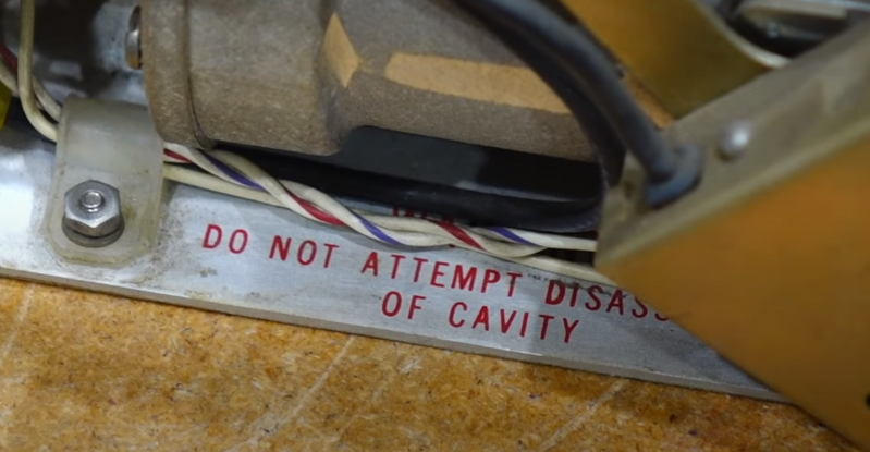
But the real beauty here is the plugin modules that gave this frequency super powers. And those modules were unfortunately manufactured with a gear grease that turned to glue after a few decades. Why does a digital frequency counter module have a clockwork component, and a metal tube with that ominous warning, “DO NOT ATTEMPT DISASSEMBLY OF CAVITY”? The tube is a resonant cavity, working as a filter. The cavity is fed with a comb generator, which generates multiple signals 10 MHz apart. The resonant filter will grab only one of the signals, giving a precise, known signal that is a power of 10 MHz. The next bit of magic in this device is a frequency mixer, which combines the test signal with this power-of-10, and outputs the difference. The resonant filter is tuned by a series of gears that move internal components. Once tuned to the nearest frequency, the difference will be less than 10Mhz, and able to be counted by the frequency counter. Just add the value shown on the dial, and you have your total frequency.

Of course, [CuriousMarc] works his magic to get things running again, not to mention doing a better job than we can explaining how the modules work. And of course, opens the forbidden fruit, and cleans that grease-turned-glue from the inner works, exploring exactly how it works, and how to get it back together. And if you want more HP 5245L goodness, maybe check out the world’s most overbuilt nixie clock.

Vintage Digital Frequency Meter Teardown

$
0
0

You think of digital displays as modern, but the idea isn’t that new. We had clocks, for example, with wheels and flip digits for years. The Racal frequency counter that [Thomas Scherrer] is playing with in the video below has columns of digits with lamps behind them. You just need the right plastic and ten lightbulbs per digit, and you are in business. Easy enough to accomplish in 1962.

Inside the box was surprising. The stack of PC boards looks more like a minicomputer than a piece of test gear. There were a few novel items inside, too, ranging from a glass-encapsulated crystal to an interesting method of selecting the line voltage.

The design seemed thoughtful. There was even a spot for spare bulbs for use when they inevitably blew out. The device has seen a few previous repairs, it seems. But with a little coaxing, it still does its job.

As high-tech as this might have been in 1962, the top range was supposed to be 300 kHz. Turns out, it was able to do quite a bit more than that. Overall, a great piece of engineering for its day and a seemingly rare instrument.

Of course, this wasn’t the only frequency counter to use this kind of display. The lights are a bit more elegant than using meters.

Simple STM32 Frequency Meter Handles Up To 30MHz With Ease

$
0
0

[mircemk] had previously built a frequency counter using an Arduino, with a useful range up to 6 MHz. Now, they’ve implemented a new design on a far more powerful STM32 chip that boosts the measurement range up to a full 30 MHz. That makes it a perfect tool for working with radios in the HF range.

The project is relatively simple to construct, with an STM32F103C6 or C8 development board used as the brains of the operation. It’s paired with old-school LED 7-segment displays for showing the measured frequency. Just one capacitor is used as input circuitry for the microcontroller, which can accept signals from 0.5 to 3V in amplitude. [mircemk] notes that the circuit would be more versatile with a more advanced input circuit to allow it to work with a wider range of signals.

It’s probably not the most accurate frequency counter out there, and you’d probably want to calibrate it using a known-good frequency source once you’ve built it. Regardless, it’s a cheap way to get one on your desk, and a great way to learn about measuring and working with time-varying signals. You might like to take a look at the earlier build from [mircemk] for further inspiration. Video after the break.


Upgrade Puts a Lot of Zeroes on Kit-Built Frequency Counter

$
0
0

If there’s anything more viscerally pleasing than seeing an eight-digit instrument showing a measurement with all zeroes after the decimal point, we’re not sure what it could. Maybe rolling the odometer over to another 100,000 milestone?

Regardless, getting to such a desirable degree of accuracy isn’t always easy, especially when the instrument in question is a handheld frequency counter that was built from a kit 23 years ago. That’s the target of [Petteri Aimonen]’s accuracy upgrade, specifically by the addition of a custom frequency reference module. The instrument is an ELV FC-500, which for such an old design looks surprisingly modern. Its Achille’s heel in terms of accuracy is the plain crystal oscillator it uses as a frequency standard, which has no temperature compensation and thus drifts by about 0.2 ppm per degree.

For a mains-powered lab instrument, the obvious solution would be an oven-controlled crystal oscillator. Those are prohibitive in terms of space and power for a handheld instrument, so instead a VCTCXO — voltage-controlled, temperature-compensated crystal oscillator — was selected for better stability. Unfortunately, no such oscillators matching the original 4.096-MHz crystal spec could be found; luckily, a 16.384-MHz unit was available for less than €20. All that was required was a couple of flip-flops to divide the signal by four and a bit of a bodge to replace the original frequency standard. A trimmer allows for the initial calibration — the “VC” part — and the tiny PCB tucks inside the case near the battery compartment.

We enjoyed the simplicity of this upgrade — almost as much as we enjoyed seeing all those zeroes. When you know, you know.

Korean Multifunction Counter Teardown

$
0
0

[Thomas Scherrer] likes to tear down old test equipment, and often, we remember the devices he opens up or — at least — we’ve heard of them. However, this time, he’s got a Hung Chang HC-F100 multifunction counter, which is a vintage 1986 instrument that can reach 100 MHz.

Inside, the product is clearly a child of its time period. There’s a transformer for the linear supply, through-hole components, and an Intersil frequency counter on a chip. Everything is easy to get to and large enough to see.

Powering it up, the display lit up readily. The counter seemed to work with no difficulties, which was a bit of a surprise.

The oscillator inside has a temperature regulator so that once warmed up, it should be more or less stable. Touching it disturbs it, but you really shouldn’t be making real measurements with the top off while you are poking around on the inside.

This would pair well with a period function generator. Compare it to a modern version.

Viewing all 30 articles
Browse latest View live


<script src="https://jsc.adskeeper.com/r/s/rssing.com.1596347.js" async> </script>